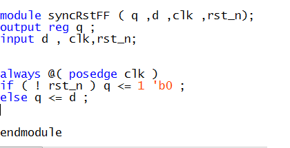
Synchronous reset flip-flops with non reset follower flip-flops
A designer should not mix resetable flip-flops with follower flip-flops (flops with no resets). Follower flip-flops are flipflops that are simple data shift registers. In the Example_1 Verilog code, a flip-flop is used to capture data and then its
output is passed through a follower flip-flop. The first stage of this design is reset with a
synchronous reset. The second stage is a follower flip-flop and is not reset, but because
the two flip-flops were inferred in the same procedural block, the reset signal
rst_n will be used as a data enable for the second flop. This coding style will generate
extraneous logic as shown in Figure 1.
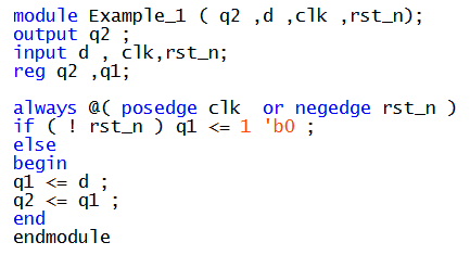
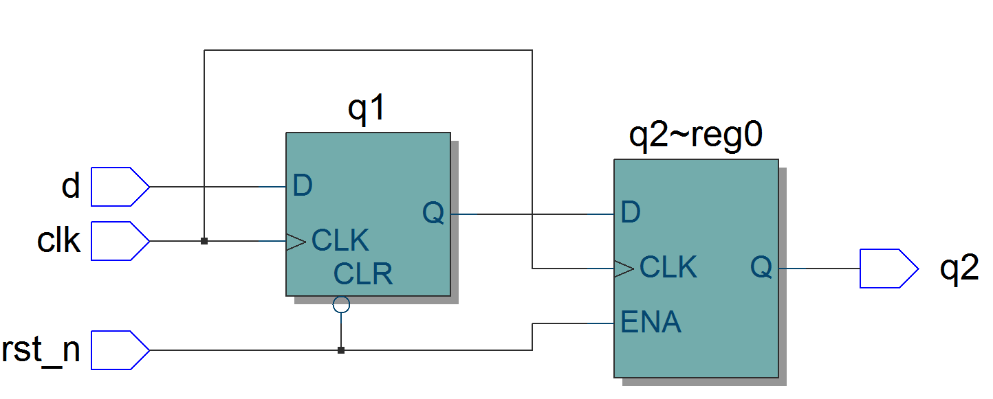
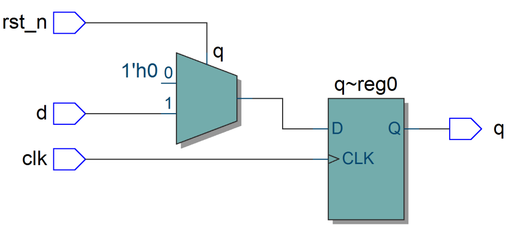
Figure 1.: Bad coding style yields a design with an unnecessary enable input at the second flip- flop .
The correct way to model a follower flip- flop is with two Verilog procedural blocks as
shown in Example_2. These coding styles will generate the logic shown in Figure 2.
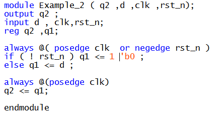
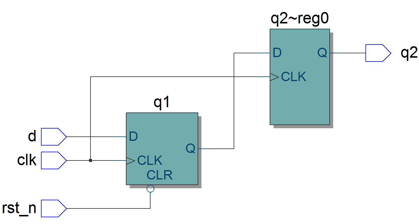
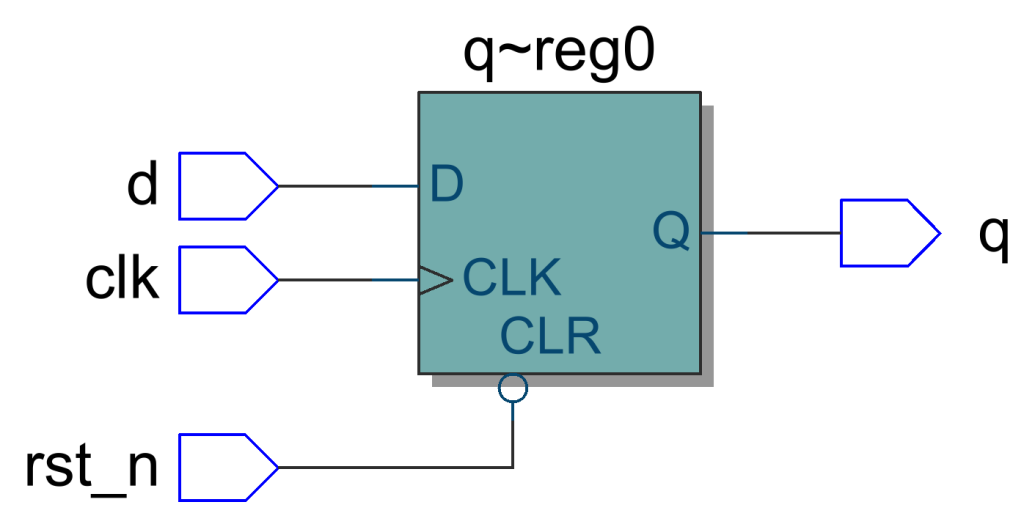
Figure 2: Two different types of FFs, one with synchronous reset and one
without. Good style of coding follower flip- flop .
Synchronous Resets
Synchronous resets are based on the theory that the reset signal will only affect or reset
the state of the flip- flop on the active edge of a clock.
Advantages of synchronous resets
- Synchronous resets generally insure that the circuit is 100% synchronous
- Synchronous resets insure that reset can only occur at an active clock edge. The
clock works as a filter for small reset glitches; however, if these glitches occur near
the active clock edge, the flip- flop could go meta stable. - In some designs, the reset must be generated by a set of internal conditions. A
synchronous reset is recommended for these types of designs because it will lter
the logic equation glitches between clocks.
Disadvantages of synchronous resets
- Synchronous resets may need a pulse stretcher to guarantee a reset pulse width
wide enough to ensure reset is present during an active edge of the clock.
When we are working with gated clock (Example GPMC interface), it is not
possible to reset the logic through a synchronous reset
Asynchronous resets
Asynchronous resets alone can be very dangerous. The biggest problem with asynchronous resets is the reset release, also called reset removal.
Advantages of asynchronous resets
- The biggest advantage to using asynchronous resets is that, as long as the vendor
library has asynchronously resetable flip- flops, the data path is guaranteed to be
clean. Designs that are pushing the limit for data path timing, can not aford to
have added gates and additional net delays in the data path due to logic inserted
to handle synchronous resets. Of course this argument does not hold if the vendor library has flip- flops with synchronous reset inputs and the designer can get
Synopsys to actually use those pins. - Asynchronous resets doesn’t require free running clock to reset the logic.
The circuit inferred for both synchronous and asynchronous reset FFs targeting altera FPGAs are depicted below. As we can see from the below circuits, in case of synchronous reset FF there is an additional combinational logic added to the data path since altera FPGAs doesn’t have FFs with synchronous reset input. This additional logic results in more data path delay and may affect the timings.

Disadvantages of asynchronous resets
- The biggest problem with asynchronous resets is that they are asynchronous, both
at the assertion and at the deassertion of the reset. The assertion is a non issue,
the de-assertion is the issue. If the asynchronous reset is released at or near the
active clock edge of a flip- flop, the output of the flip-flop could go meta stable (Unknown state). - Another problem that an asynchronous reset can have, depending on its source, is spurious resets due to noise or glitches on the board or system reset.
Asynchronous reset problem
As shown in Figure 3, an asynchronous reset signal will be de-asserted asynchronous
to the clock signal. There are two potential problems with this scenario: (1) violation of
reset recovery time and, (2) reset removal happening in different clock cycles for different sequential elements.
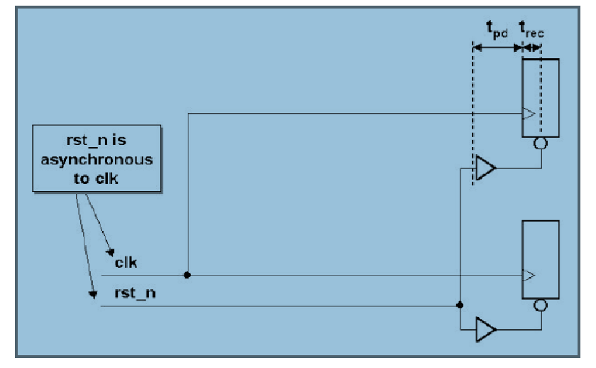
Reset recovery time
Reset recovery time refers to the time between when reset is de-asserted and the time
that the clock signal goes high again. Recovery time is also referred to as a tsu setup time
of the form, PRE or CLR inactive setup time before CLK edge. Missing a recovery time
can cause signal integrity or metastability problems with the registered data outputs.
Reset removal traversing different clock cycles
When reset removal is asynchronous to the rising clock edge, slight differences in propagation delays in either or both the reset signal and the clock signal can cause some flip-flops to exit the reset state before others.
Reset synchronizer
Note:- EVERY ASIC/FPGA USING AN ASYNCHRONOUS RESET SHOULD
INCLUDE A RESET SYNCHRONIZER CIRCUIT!!
Without a reset synchronizer, the usefulness of the asynchronous reset in the final system is void and dangerous even if the reset works during simulation.
The reset synchronizer logic of Figure 4 uses two flip flops to achieve reset synchronization of an asynchronous reset. An external reset signal asynchronously resets a pair of master reset flip- flops, which in turn drive the master reset signal asynchronously through the reset buffer tree to the rest of the flip- flops in the design. The entire design will be asynchronously reset.
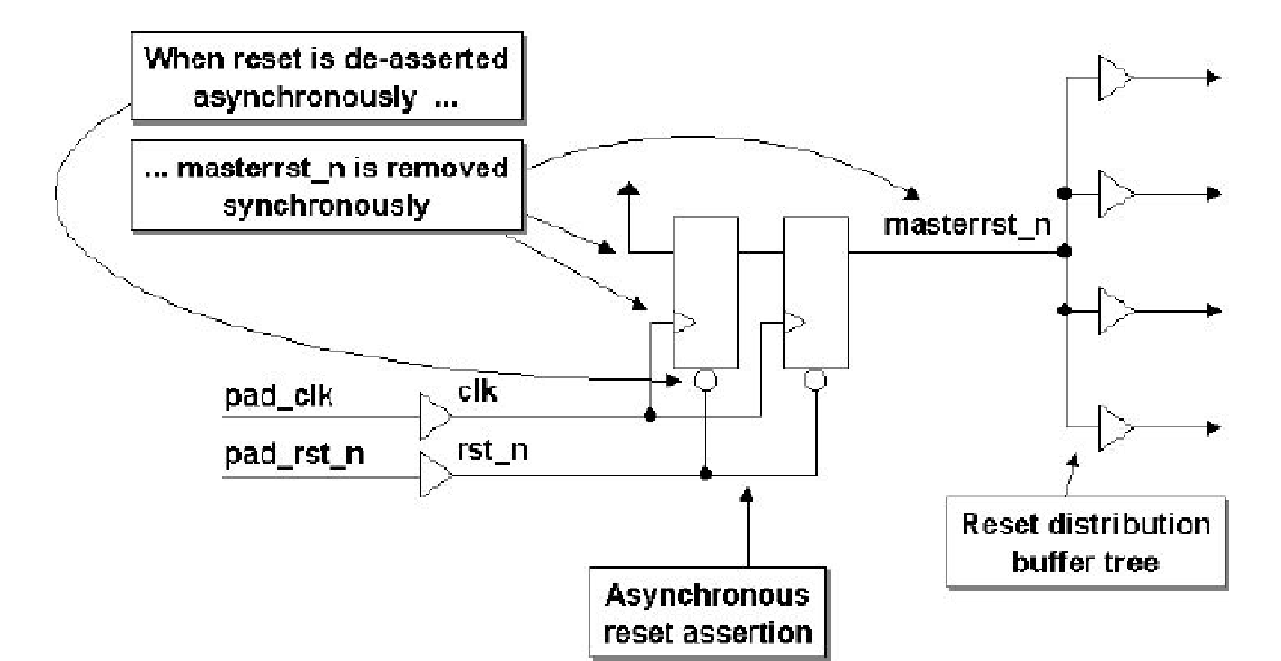
Reset removal is accomplished by de-asserting the reset signal, which then permits the
d-input of the rst master reset flip- flop (which is tied high) to be clocked through a reset
synchronizer. It typically takes two rising clock edges after reset removal to synchronize
removal of the master reset.
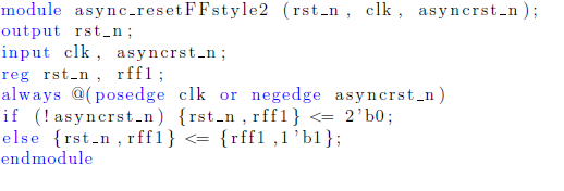
First flip- flop is required to synchronize the asynchronous reset signal to the receiver clock domain where the second flip- flop is used to remove any metastability that might be caused by the reset signal being removed asynchronously and too close to the rising clock edge.

Leave a comment